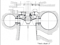
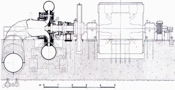
Francis
Francis turbines (James Bicheno Francis) belong to the category of reaction machines.
The runner is fed with water under pressure because only one portion of the available head has been transformed into speed by means of the wicket gate. The reaction degree is defined as the difference between the available head and the head that has to be still transformed at the runner inlet, and can be expressed as ![]() [8]
[8]
Having indicated with H the available net head and with V1 the water speed at the runner inlet (fig. 1). On average, the reaction degree corresponds to 0.7 ÷0.8. One portion of the head operates on the runner inlet by IMPULSE, that is the one transformed into speed at the wicket gate outlet, while the remaining portion operates by REACTION.
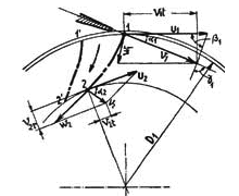
Fig 1
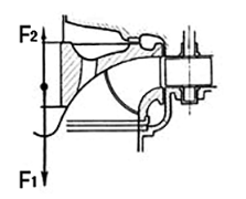
Fig 2
In Impulse (Pelton) turbines, the axial thrust transmitted from the wheel to the motor shaft is null, on the contrary, in REACTION turbines one component of the axial thrust F1 is generated by the difference of motion quantity between runner inlet and outlet and has opposite direction with respect to the water discharge. Another thrust F2, generally of opposite direction with respect to the previous one and then following the way of the water, and of a much higher value, is the one that take place between runner and covers (fig. 2), to which, in case of vertical units, we must add the weight of the rotating parts.
![]() F=F1-F2
F=F1-F2
There are various expedients to decrease the value of F, as for example to perform, where possible, holes on the runner crown with the purpose to put in touch the area under pressure with the one in depression at the runner downstream (fig. 2), or to adopt compensation pipes on the upper cover to put in touch the area between runner and cover with the outside environment under atmospheric pressure or in touch with the draft tube situated just below the runner where there is depression, and so on. In most cases, to nullify the thrust F it we adopt the thrust bearings. Differently from Pelton turbines, it is much more difficult to determine the diameter of the Francis runner, even if in first approximation. In the spirit and in the limits of this site, we propose the following table that will give a first indication about the runner dimensions. See (fig 4). Being ![]() [9] and so for the other U relevant to the corresponding diameters. Zd is the number of gates and a0 is the maximum circle between two contiguous gates in rated opening position.
[9] and so for the other U relevant to the corresponding diameters. Zd is the number of gates and a0 is the maximum circle between two contiguous gates in rated opening position.
| nq | 15 | 30 | 40 | 55 | 70 | 80 | 95 | 110 |
| 0,65 | 0,686 | 0,745 | 0,828 | 0,920 | 1,020 | 1,130 | 1,240 | |
| 0,65 | 0,686 | 0,70 | 0,70 | 0,70 | 0,70 | 0,70 | 0,70 | |
| 0,40 | 0,495 | 0,633 | 0,78 | 0,92 | 1,04 | 1,155 | 1,27 | |
| 0,34 | 0,358 | 0,37 | 0,38 | 0,39 | 0,4 | 0,405 | 0,41 | |
| 0,05 | 0,150 | 0,175 | 0,225 | 0,27 | 0,315 | 0,35 | 0,39 | |
| 0,525 | 0,690 | 0,85 | 0,995 | 1 | 1,02 | 1,022 | 1,025 | |
| 0,80 | 1,15 | 1,45 | 1,65 | 1,82 | 1,95 | 2,07 | 2,15 | |
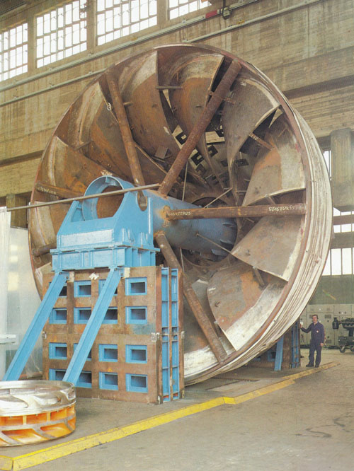
Fig 3 Francis runner
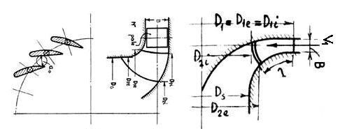
Fig 4
Example:
Calculate the main dimensions of one Francis runner that operates under the following data:
H=130 m Q= 15 m3/s n=428 rpm µ= 92%
The power output at the turbine shaft is (formula [a]) N= 17600 Kw and the characteristic speed nq=43 ( formula [b] ).
From the table ![]() =0,75 (about) and taking into account of (9), we obtain D1e= 1,68 m and going on with the data of the table, we obtain in the same D1i=1,58 m, D2e=1,43 m, D2i=0,83 m, B=0,295 m, Ds= 1,43 m. We choose Zd = 20 gates (*), a0=0,122 m. The speed the water reaches when it comes out from the gates when the machine is at full load is
=0,75 (about) and taking into account of (9), we obtain D1e= 1,68 m and going on with the data of the table, we obtain in the same D1i=1,58 m, D2e=1,43 m, D2i=0,83 m, B=0,295 m, Ds= 1,43 m. We choose Zd = 20 gates (*), a0=0,122 m. The speed the water reaches when it comes out from the gates when the machine is at full load is ![]() =21 m/s and neglecting the leaks through the wicket gate at the runner inlet we can consider V0=V1 and then the reaction [8] degree results to be f=0,8.
=21 m/s and neglecting the leaks through the wicket gate at the runner inlet we can consider V0=V1 and then the reaction [8] degree results to be f=0,8.
Note. The values expressed in the table are merely indicative and have the only purpose to give an idea of the dimensions the hydraulic channel may reach.
(*) The ratio between number of gates and number of runner blades shall no be a whole number in order to prevent pulsations. In the previous example, if we suppose 13 runner blades also Zd= 24 is a correct value.

