Kaplan
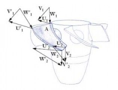
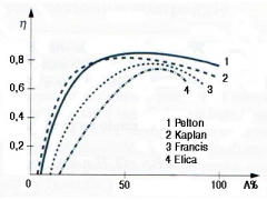
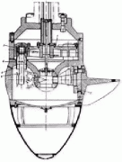
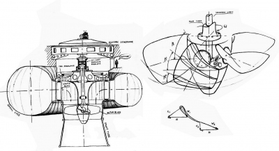
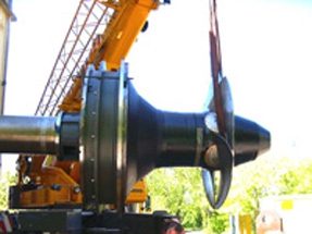
When one Francis turbine of mean/large power output is designed to operate under a low head, suppose of 15 m, typical for installations on big rivers, the discharge should be of at least 150 m3/s to obtain a power output of about 20 MW, having assumed the efficiency µ = 93%. For example, head variations of 15% between minimum and maximum are typical of Francis turbines, even if there cases with much more significant variations. When one powerhouse is located on a river, the head variations are much more than 15% and reach on average about 50%. These variations remarkably affect the good operation of one Francis turbine, whereas they are well tolerated in Kaplan turbines that have the possibility to make use of a double regulation realized by means of the gates, as in Francis turbines, in synchrony with the runner blades that rotate around the stems positioned inside the hub (fig. 3) by means of link-handle mechanisms, controlled on their turn by a servomotor placed inside the hub itself or obtained between the shaft connections. The possibility of the double regulation allows having efficiency curves that are much wider than those of Francis and propeller (Kaplan with fixed blades) machines (fig. 2), because the blades are going to take the most suitable position in accordance with the variation of the speed triangles (fig 1).
Kaplan turbine is usually used within the range of 95< nq <275
We indicate by K the peripheral speed coefficient which variation range is between 1,25< k<2,5. If we assume n11= 84,5 K (the demonstration would go beyond the purpose of this synthesis), we can write 105<n11<210 and, on the basis of the following table, determine the runner diameter and the other characteristic quantities of the turbine.
| nq |
95
|
110
|
125
|
135
|
150
|
165
|
180
|
190
|
205
|
220
|
230
|
245
|
260
|
275
|
| K |
1,24
|
1,31
|
1,39
|
1,48
|
1,56
|
1,65
|
1,75
|
1,85
|
1,94
|
2,04
|
2,14
|
2,25
|
2,36
|
2,48
|
| n11 |
104
|
110
|
116
|
123
|
130
|
137
|
145
|
154
|
162
|
170
|
178
|
187
|
197
|
207
|
|
0,36
|
0,365
|
0,372
|
0,38
|
0,386
|
0,392
|
0,4
|
0,406
|
0,412
|
0,42
|
0,426
|
0,432
|
0,44
|
0,45
|
|
|
1,7
|
1,84
|
2
|
2,12
|
2,26
|
2,38
|
2,5
|
2,6
|
2,7
|
2,8
|
2,88
|
2,95
|
3,04
|
3,1
|
|
EXAMPLE
Given the following values: H = 30 m Q = 400 m3/s n = 94,74 rpm ( f= 60 Hz)
With so big turbines, we may expect high efficiencies and in this case we assume µ = 94%. The power output at the turbine shaft will be: N= 110650 Kw (Fundamentals [a]) nq=150 (Fundamentals [b]) and from the table we obtain n11= 130. Taking into account that we:
n11=![]() (Fundamentals) si ricava D= 7,5 m.
(Fundamentals) si ricava D= 7,5 m.
Looking again at the table:
B/De = 0,386 and then B = 2,9 m (fig 4). Again zda0/De = 2,26 and with zd=24 (number of gates) a0=0,7 m opening between the gates ( Francis ) (fig 4). In general the hub may be assumed equal to 0.45D, depending on the number of runner blades and on the stresses it undergoes. Under the head of 30 m, we can use one runner with 5 blades and the diameter of the hub shall be roughly Dm= 3,4 m.
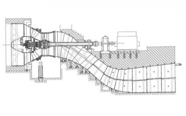
The Kaplan turbines include the S turbines. They are so called because of the shape of the draft tube. They are characterized by low heads e quite big flows. Low heads oblige then to adopt a horizontal arrangement.
Fig. 6 shows one turbine of this type having the following characteristics:
Net head…………………….. 9 m Max discharge…………………… 40 m3/s Turbine shaft power output …. 3,27 MW Rated turbine speed… 150 rpm Generator speed………… 750 rpm
If we observe the figure, we can see the conical distributor, the Kaplan type runner, the bearing at the outlet of motor shaft from the discharge, and then an adjustable joint to compensate any possible disalignment, the speed step up gear that brings the turbine rotation from 150 to 170 r.p.m. and the generator. In absence of the step up gear, the size of the generator would be much bigger.
